Temperature Control
Hot Plate Stirrer Troubleshooting Guide
November 6, 2024
Technical Team
Technical Guide
Article Summary
Complete troubleshooting procedures for Cole-Parmer hot plate stirrers including error codes, temperature calibration, and safety protocols.
# Hot Plate Stirrer Troubleshooting Guide
## Technical Overview and Specifications
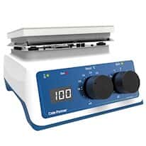
Cole-Parmer hot plate stirrers, including the StableTemp® SHP-200 and SHP-300 series, combine precision temperature control with magnetic stirring capabilities. Technical specifications:
- **Temperature Range**: Ambient to 350°C (ceramic top), 300°C (aluminum)
- **Temperature Accuracy**: ±1°C at set point with external probe
- **Stirring Speed**: 100-1500 RPM continuously variable
- **Platform Size**: 6.5" x 6.5" to 10" x 10" depending on model
- **Power Rating**: 500W to 1500W heating capacity
- **Control Type**: Digital PID with microprocessor control
- **Safety Features**: Over-temperature protection, hot surface indicator
## Safety Warnings and Precautions
⚠️ **BURN HAZARDS**
- Hot surfaces can cause severe burns even after power-off
- Always use heat-resistant gloves when handling vessels
- Allow minimum 45-minute cooling before maintenance
- Hot surface indicator must be functional at all times
⚠️ **ELECTRICAL SAFETY**
- Never immerse unit or allow liquids to contact electrical components
- Inspect power cord daily for heat damage or cracking
- Use appropriate electrical protection in laboratory environments
- Ground fault protection required for wet laboratory applications
⚠️ **CHEMICAL SAFETY**
- Ensure adequate ventilation when heating volatile chemicals
- Never heat flammable solvents above flash point
- Clean spills immediately to prevent platform damage
- Use appropriate spill containment for hazardous materials
⚠️ **FIRE PREVENTION**
- Never leave unit unattended during heating operations
- Install over-temperature safety limits for all applications
- Keep combustible materials away from hot surfaces
- Maintain clear access to emergency shutoff controls
## Error Code Table and Diagnostic Actions
### Digital Display Error Codes
| Error Code | Description | Probable Cause | Diagnostic Action |
|------------|-------------|----------------|-------------------|
| **Er1** | Sensor Open Circuit | Probe disconnected or damaged | Check probe connections; test sensor continuity |
| **Er2** | Sensor Short Circuit | Moisture in probe or damaged wiring | Dry connections; test insulation resistance |
| **Er3** | Over-Temperature | Safety limit exceeded | Check cooling; verify temperature probe accuracy |
| **Er4** | Heating Element Fault | Element failure or control circuit | Measure element resistance; check relay contacts |
| **Er5** | Control Circuit Error | Microprocessor or memory fault | Power cycle; check for EMI interference |
| **Er6** | Calibration Error | Invalid calibration data | Perform factory reset; recalibrate temperature |
| **Er7** | Communication Fault | Display/control board connection | Check ribbon cable; reseat connectors |
## Common Failure Modes and Diagnostic Procedures
### 1. Inadequate Heating Performance
**Symptoms:**
- Unable to reach set temperature within reasonable time
- Temperature overshoots or oscillates around set point
- Uneven heating across platform surface
**Diagnostic Steps:**
1. **Heating Element Testing**
- Disconnect power and allow complete cool-down
- Measure element resistance with ohmmeter (should be 25-75Ω depending on wattage)
- Check for element-to-ground shorts (>10MΩ insulation resistance)
- Visual inspection for element cracks or discoloration
2. **Temperature Sensor Verification**
- Test sensor accuracy with calibrated reference thermometer
- Check sensor resistance vs. temperature curve (RTD: 100Ω at 0°C)
- Verify sensor mounting and thermal contact
- Test sensor cable for continuity and insulation
3. **Control System Testing**
- Monitor heating element voltage during operation (should be near line voltage)
- Check solid-state relay switching with oscilloscope
- Verify PID control parameters are within specification
- Test temperature control algorithm response time
### 2. Stirring Function Failures
**Symptoms:**
- Magnetic stirring stops or becomes erratic
- Stir bar decouples from magnetic field
- Speed control ineffective or nonlinear
**Diagnostic Steps:**
1. **Magnetic Drive System**
- Test magnetic field strength at platform surface (800-1200 Gauss)
- Check magnet assembly for damage or debris
- Verify motor coupling integrity
- Test stirring motor electrical connections
2. **Speed Control Circuit**
- Measure speed control potentiometer resistance curve
- Test PWM output signal to motor drive circuit
- Verify encoder feedback signals (digital models)
- Check motor current draw under various load conditions
## Detailed Step-by-Step Repair Procedures
### Temperature Calibration Procedure
**Required Equipment:**
- NIST-traceable reference thermometer (±0.1°C accuracy)
- Calibration bath or dry-block calibrator
- Temperature-stable test medium (high-viscosity oil)
**Calibration Setup:**
1. **Environmental Preparation**
- Ensure stable ambient temperature (20°C ±2°C)
- Allow unit to stabilize for 30 minutes before calibration
- Use vibration-free surface for maximum stability
- Provide adequate ventilation for heat dissipation
2. **Reference Standard Preparation**
- Verify reference thermometer calibration certificate (current within 12 months)
- Check thermometer for damage or contamination
- Record reference thermometer correction factors
- Prepare temperature-stable test medium
**Multi-Point Calibration Process:**
1. **Low Temperature Point (100°C)**
- Set hot plate to 100°C using external probe mode
- Place reference thermometer adjacent to control probe
- Allow 15-minute stabilization period
- Record displayed temperature vs. reference reading
- Calculate offset correction factor
2. **Mid-Range Point (200°C)**
- Increase set point to 200°C
- Allow 20-minute stabilization for thermal equilibrium
- Record readings every 2 minutes for 10-minute period
- Calculate average deviation from reference standard
- Document control stability (±1°C maximum variation)
3. **High Temperature Point (300°C)**
- Set final calibration point at 300°C
- Allow extended stabilization (30 minutes minimum)
- Monitor for control oscillations or overshoots
- Record final calibration data and correction factors
- Verify safety shutdown functions at high temperature
**Calibration Adjustment Procedure:**
1. **Access Calibration Mode**
- Power down unit and disconnect external probe
- Hold SET and START buttons while powering up
- Enter technician access code if required
- Navigate to temperature calibration menu
2. **Enter Correction Factors**
- Input offset corrections for each calibration point
- Verify linear interpolation between calibration points
- Save calibration data to non-volatile memory
- Exit calibration mode and restart unit
3. **Verification Testing**
- Repeat temperature measurement at all calibration points
- Confirm accuracy within ±1°C specification
- Test control stability over 2-hour period
- Document calibration results and affix calibration label
### Heating Element Replacement
**Required Tools:** Phillips screwdrivers, multimeter, thermal compound, gasket material
**Safety Preparation:**
- Disconnect all power and lock out electrical supply
- Allow minimum 2-hour cooling period
- Remove all glassware and accessories from unit
- Prepare clean, static-free work area
**Disassembly Procedure:**
1. **Top Platform Removal**
- Remove platform mounting screws (typically 6-8 screws)
- Lift platform carefully to avoid damaging gasket surfaces
- Document wire routing with digital photographs
- Clean mounting surfaces with isopropyl alcohol
2. **Element Access and Removal**
- Disconnect element electrical connections (note wire positions)
- Remove thermal insulation material
- Extract old heating element (may require gentle heating to soften sealant)
- Clean element mounting area thoroughly
**Installation Procedure:**
1. **New Element Preparation**
- Verify element specifications match original (wattage, voltage, resistance)
- Check element for physical damage or contamination
- Apply thin layer of high-temperature sealant to mounting surface
- Position element ensuring even contact across mounting area
2. **Electrical Connection**
- Connect element leads using high-temperature wire nuts or crimp connections
- Verify proper wire routing to avoid contact with hot surfaces
- Test electrical connections with ohmmeter (element resistance within 5% of specification)
- Install thermal protection devices if equipped
3. **Reassembly and Testing**
- Replace thermal insulation ensuring complete coverage
- Install platform with new gasket material
- Torque mounting screws to specification (typically 15-20 in-lbs)
- Perform initial heating test at low temperature (100°C)
- Monitor for unusual odors, smoke, or hot spots during first heating cycle
## Preventive Maintenance Schedule
### Daily Operations
- **Visual Inspection**: Check platform for cracks, stains, or damage
- **Safety Verification**: Ensure hot surface indicator functions properly
- **Cleaning**: Wipe platform surface with appropriate cleaning solution
- **Control Test**: Verify temperature and stirring controls operate smoothly
### Weekly Maintenance
- **Electrical Check**: Inspect power cord for heat damage or cracking
- **Ventilation**: Clean air intake vents and cooling passages
- **Calibration Check**: Verify temperature accuracy with reference thermometer
- **Documentation**: Record operating hours and any unusual observations
### Monthly Service
- **Deep Cleaning**: Remove platform and clean internal components
- **Connection Inspection**: Check all electrical connections for corrosion or looseness
- **Function Testing**: Test all control modes and safety systems
- **Performance Verification**: Conduct heating rate and temperature stability tests
### Annual Maintenance
- **Complete Calibration**: Full multi-point temperature and stirring speed calibration
- **Element Inspection**: Check heating element condition and resistance
- **Safety System Test**: Verify over-temperature protection and emergency shutoffs
- **Professional Service**: Consider factory service for high-usage units
## Professional Service Recommendations
**Factory Service Required For:**
- Heating element replacement requiring precision machining
- Electronic control board repair or replacement
- Safety system calibration and certification
- Warranty repairs requiring factory authorization codes
**Service Documentation Requirements:**
- Complete maintenance history with calibration records
- Operating environment conditions and chemical compatibility data
- Failure mode description with photographic documentation
- Previous repair attempts and component replacement history
Contact Cole-Parmer technical support for nearest factory-authorized service facility. Provide model number, serial number, and detailed failure description for expedited service scheduling.
Need Additional Support?
If you're experiencing issues not covered in this guide, our technical team is here to help.
Contact Technical Support